Creating the box
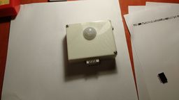
After fixing the power related issue I encountered…I designed a box for the device; which could be 3d printed.
I’ve started working with some nightly FreeCad version (v0.16) - I ended up using a the nightly version because I encountered some issue with its spreadsheet usage - I worked a lot to be able to enter all my data thru the spreadsheet page. So later I can come back, and this way I don’t have to be absolutely right at the first time - just change the parameter and I’m done - at least that’s the idea…FreeCad is designed for heavy use of constraint based modelling - it takes a lot of effort do design things in it.
It have taken more than an evening to design the box…but after I’ve sent the plans to my friend for review&print…it turned out that my screw sizes might be too big - i changed the parameter in the spreadsheet - and I was sure I’m done…but it turned out that the constraint based machinery have failed…I ended up burning a whole hour to fix the issue which was caused by a very annoying fact/bug.
The Silver bullet of constraint based modelling (for me at least)
It works fine until there is only a finite number of solutions to some skecth…by finite i mean:
- new sketch
- new point (P)
- add constraint: P is on axis X
- add constraint: distance of P and O is 50mm
now…i think it’s obvious that this sketch has 2 valid solutions…but the only way i can switch between these two solutions is by removing the distance constraint, move the point and add the constraint again.
Freecad tries hard to follow changes and update the scetch with the best it can come up with…but when I change some basic parameter; the solver have to do the picking from these finite number of solutions…which may end up being not what the user wanted.
Alternatives for FreeCad
After these troubles with freeCad i’ve looked into the alternatives (which I’ve encountered earlier; when i’ve chosen freecad for the job). And i’ve taken a more closer look on OpenSCAD.
It works by writing some geometry generating code…which is fine; this way i don’t even need the spreadsheet anymore - I will just add some variables.
I was able to create almost the entire box model in openscad in much less time; but I was unaware of some design constraints…but after fixing them it looked fine.
What I really miss, is freecad’s drawing output; which enabled me to print some projections on paper to check my design.
Assembling the “product”
So…after i’ve “fixed” some minor issues with the box’s design…Alex have printed it ;) I never seen 3d printed stuff earlier…but it’s amazing to see a 3d model in real 3d.
I was happy to have a working board and the box is ready for it’s encapsulation…but I’ve had to add the missing wires/etc for the sensors…when i designed the box, I’ve placed the dht22 and the photoresistor to the outside the box…and the legs of the dht is not long enough to connect anything to it inside the box…so i’ve tried to make it longer, by donating “legs” from a few resistors…these leg extensions broke almost always I’ve tried to install it inside the box - this method is very fragile (and I’m an amateur ;) but…at least the photoresistor went seemlessly.
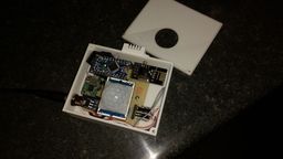
After I’ve placed everything inside the box..i’ve connected the power and checked with my desk arduino for what it’s measuring…but for my greatest surprise; it dosen’t give any signals…or at least this was what i’ve thinked…after at least half an hour…i disassembled the instrument, checked the nrf connections…added extra spacing wires for the nrf…i’ve enabled the debug mode for the both of the nrf modules; and then the recieving channel of my desk instrument looked very bad…it turned out that i’ve refactored the code…to let all my devices share the same parts…but i’ve not set the test reciever to “listen” for anyone…
After it worked; i’ve (almost) closed the box…it was a mistake to use only 2 screws.
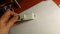
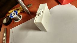
For preview purposes…I’ve temporarily installed it in its desired location with the help of a pencil ;)

Even thru I was able to produce a working prototype…I might create a new one at a later time - the installation procedure is not as easy as I thinked earlier.
What i’ve learned from this ;)
- drill bigger holes…and at least check that I do have the screws with the designed size ;)
- my ~2mm walls are a bit too thick for the printer.
- find a different way to install the dht…it might worth the effort to build a small socket for dht - it’s no big deal, because it’s 3d printed anyway.
- make more space under the board
- the board should not cover the suspension holes/screwes - if I would like to place this at its desired location; I would have to almost fully disassemble the thing and reassemble it’s internals after the box have been placed.
- i should use linear regulators next time…
- remove the power/etc leds from it…because it’s bright enough to be seen thru the box.